So I did end up generating another new page today, why not. The page covers PWB headers, or maybe the start to the definition of PWB headers. Any way it was generated to hold a few graphics of board headers, which is why it received it's own page. Like many new posts here, this new page has little or no text but I'll add it in a few days. The only link so far is from the Header Definition page.
A few other dictionary pages that have no hits;
Residual Current Device.
COTS Definition.
Balun Definition.
Pulse Shape Definition.
And so on, just a few page links wit no page rank and no page visits this year.
err last post of the year.........
Thursday, December 31, 2009
Headers
Wednesday, December 30, 2009
Resistor Definitions

At this point there are a number of pages that cover different resistor topics. Here are a few with the lowest page views this year [should be all new page additions]:
8-pin SIP Resistor Networks [un-common].
8-pin SIP Resistor Networks [also un-common].
I've never seen either of these resistor configuration in those SIP packages, but that doesn't mean some one may need them one day.
20-pin LCC Resistor Network Schematics.
SIP Dual Termination Resistor Networks.
Those four pages were some what new, here's a few older pages with no page rank.
MIL-R-39015 Resistor Derating. [Wire-Wound]
MIL-R-83401 Resistor Network Derating.
MIL-R-55182 Resistor Derator Curve.
There's a few more than that, but I'm not really sure why they do not have a page rank.
Looks like the pages have a number of internal links from other pages about Resistor, but no external links. However I just checked they are listed in the site map, but that sitemap may be to large a file for Google to read [they like 100 links or less a page].
There are a few other resistor graphics I have but I don't think I'll get them in by the end of the year. Looks like there's around 50 pages that relate to resistor issues.
Not sure why but the Current Sense Resistors page didn't show very high in a search.
Graphic 16 pin Gull-Wing Surface Mount Package [used with resistor networks].
Tuesday, December 29, 2009
Fuse Block Holder

Other related pages include;
Fuse Manufacturers. [Fuse Vendors]
How to Derate a Fuse.
DC Operation of Fuses.
Circuit Breaker Manufacturers. [CB Vendors]
Looks like the Fuse derating page was added back in May [Rackmount Computers] and the page on DC Fuse operation was added in April [Maximum Fuse Voltages].
I should be able to update the Fuse Block page some time today.
The data on panel mount fuse holders needs to be removed. A Fuse Block is used inside a chassis while the Panel Mount fuse is located on the chassis wall.
Graphic; Panel Mount Fuse Holder.
Monday, December 28, 2009
Transistor Array Packages
I added a new page showing a few different types of Transistor Arrays. It's linked off the dictionary page for Array.
Here are a few related pages which only received a few page views this year:
How to derate a 2N3967 transistor.
How to derate a 2N2432 transistor.
How to derate a 2N2604 Transistor.
2N6758 Field Effect Transistor derating.
TO-66 Transistor Package.
Device Under Test definition.
In fact many of the pages that received less that a few dozen hits over the entire year relate to Transistor Derating. But it's hard to make a page on a part number, try searching for a part number and you get hundreds of computer generated pages with rows of part numbers.
Friday, December 25, 2009
TVS Arrays

If the internet ever comes back on-line I may be able to get another page updated. Google has been up and down sense last night. I've been trying to make this posting sense last night too.
So far this year 4,028,610 pageviews for interfacebus.
Graphic; 20 pin DIP package.
Wednesday, December 23, 2009
Tee Connector Diagrams

I also added a number of links to other related definitions;
Definition of BNC Connector.
Definition of SMA Connector.
Dummy Load Definition.
The new page shows three coax connectors; a BNC Tee and two TNC Tee connectors.
Reference; Banana Jack Definition. Coax Definition.
Related; Chassis Connector Selection,
Graphic; BNC to Banana Jack connector picture.
Surface-mount Trimmer Resistor Packages

Both pages use the links to Resistor Terms at the top of the page; As in these definitions:
Adjustable Resistor.
Lead-Screw Resistor.
Non-Wire Wound Resistor.
Potentiometer.
Reostat.
Trimmer Resistor.
Variable Resistor.
The page covering companies that Manufacturer Potentiometers works off the link. There also also links to Derating Potentiometers, and Wire-Wound Potentimeter Derating. There are dozens of other pages relating to resistors and Trimmers.
A Trimmer is a variable resistor that is produce that only supports a full adjustments, a trimmer is not made to handle continuous adjustments or changes. Each of those two pages show four or five different examples of package styles.
Graphic; Variable Resistor, Wire-Wound Derating Curve [MIL-R-39015].
Friday, December 18, 2009
Feed-Through Capacitors

The new page covers Feed-Through Capacitors or Feed-Through filters, depending on who you talk to.
The page started as a copy of this page Capacitor Terms, or at least a starting place. And I already see that I didn't add that pages link back on the page..
I also added a link off the RFI Shielding page.
Tuesday, December 8, 2009
Types of Resistor Trimmer Packages

I'll add another page to cover a few surface mount packages soon.
Looks like there's a page for Potentiometer derating, but not one for how to derate a trimmer.
Graphic; 4mm square surface mount gull wing trimmer.
Monday, December 7, 2009
IC Encoders and Converters
Just like the last few page additions, these new links were added to the Functional Schematics page.
The first page covers an Excess-3 Code to Decimal Decoder. I'm a bit unsure what the difference is between an Encoder or Decoder. Couldn't any Encoder be considered a Decoder, depending on if the input or output is being referenced?
Anyway the second addition was for a variation of the same thing; an Excess-3 Gray code to Decimal Decoder.
I also added a link from the 'Ex' Definitions page. I may also add a link to the Definition of Encoders page. Looks like this page is missing a Decoder Definition.
It appears there are now 23 pages in this new section of IC functional diagrams.
Sunday, December 6, 2009
Integrated Circuit Functional Diagrams

I think I also added a page on DIP Switches, or maybe it was last night.
It's not all about three new pages that will see little or no visits, 23 other pages were updated today.
The graphic is a AND-OR Carry Function from a counter.
Saturday, December 5, 2009
Who makes Analog Switches

Not much to either of those pages but the pin out information for a 14-pin DIP package. But it's another data page in support, so the addition doesn't hurt.
Graphic; Dual Function Single Position Double Throw Analog Switch.
Thursday, December 3, 2009
Dual Leadless Chip Carrier Resistor Array

Graphic; Resistor Array xN package.
Monday, November 30, 2009
Non-Standard Resistor Networks

So any way I added two new pages both showing non-standard resistor pin outs in an 8-pin Single Inline Package:
Non-Standard Resistor Networks.
Uncommon Resistor Networks.
Guess I'm getting to the point I need to add an upper level page to link to all these new related additions.
Of course it's not all about adding new pages; this month the site received over 80 new graphics, on at least that many pages. In addition; my computer indicates over 500 pages were updated, to some degree. However many page up-dates may have been an HTML update being made to a number of pages.
It would seem that over 30 new pages were added this month, out of that 500 page update.
So 500 page updates, of which 30 were new pages, with some 80 new pic files. Of course this blog normally only indicates new page additions and not new pick files or updates.
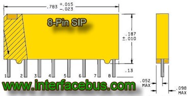
Graphic; 8 pin SIP Resistor Network.
Sunday, November 29, 2009
SIP Resistor Networks
6-pin SIP Resistor Network,
8-pin SIP Resistor Network,
10-pin SIP Resistor Network.
This time the components are divided by schematic and not package. So, for example, the bused resistor network is shown on one page, with pinouts for each of the SIP layouts;
SIP Bused Resistor Network. [Common Tie point]
SIP Isolated Resistor Network. [Individual Components]
SIP Dual Termination Resistor Network. [Thevenin]
Looks like there are two general styles of packaging. A molded package and a conformal coated version. The page on SIP Packages shows both package styles.
I also just added a few other pages; one for Non-standard resistors in a 6-pin SIP, and one for a 14-pin DIP Resistor Network. They were all uploaded about an hour ago, but I have to many 'in-work' pages so I'll go ahead and stop for now. I may go ahead and update them again, but will not add any other related pages today. Five new pages works......
Graphic; 8 pin through-hole Single In-line Package [SIP] used with Resistor Networks.
Saturday, November 28, 2009
What are the different types of Resistor Networks

Anyway I added a new page to cover Resistor Networks in a 20-pin Leadless Chip Carrier [LLCC], or 20-pin LLCC Resistor Networks. I then added one to cover 16-pin LLCC Resistor Networks. I think most of the text is all the same on each of the pages. All the schematics are the same, except for the pin out and the packages so why wouldn't the text be the same.
I just noticed that the dual-resistor termination package in a 16-pin LLCC case only has seven termination resistors, what bus uses just 7 bits of data? Same thing with the common-pin package which only has 15 resistors.
So now there's a page for 16-pin DIPs, a 16-pin LCC and a 20-pin LCC package each with three different styles of resistor interconnections.
Design hint. Resistor Networks are great because they save a lot of board space, but there are problems with these components.
First noise is easily passed from one resistor to the next because they are all in the same package.
Secondly, one resistor [in the package] my be located in the correct spot on the PWB, but in many cases all other traces need to be routed out of their way to reach the resistor package. Individual resistor packages can be placed in the exact location required, resistor networks can not. This may not matter in low speed systems but in high speed networks trace distance does matter.
Friday, November 27, 2009
Component Derating Guidelines

It was just random chance that I added a picture of a 2N3637 SOA in this posting. I already had a page covering that topic out on Google Sites; Maximum Safe Operating Area.
Normally I don't post new pages added to Google Sites, but I did add two pages today [no text yet]. The internal Construction of a Capacitor, and the internal Construction of a Resistor.
Any other page changes [to either site] today were just small updates.
Graph; Safe Operating Area [SOA] Power Curve, 2N3637 Transistor.
Functional IC Schematics

A page was added to include a Shift Register circuit, with component part numbers. Also one to include a Parity Checker or Parity generator circuit, with just a few part numbers. Another page includes Flip Flop gates. This one does not include gates with Output Enable lines, so I may add another page later to include those types of flip flops.
To support the page on Decoder chips, a page was adder for Encoder Chips. But neither page provides IC part numbers, at least for now.
I think I also added a page on Binary Adders. I may have also added a listing of Analog Switch ICs. Might be about it. As normal, I'll add some more data in a few days. Semiconductor manufacturers, and Standard Logic manufacturers.
Graphic: Dual Analog Switch in a Dual In-Line package, with pinout.
Thursday, November 26, 2009
IC Schematics

Although I didn't have a circuit diagram for an Analog Switch, I did add one for an Analog Multiplexer IC. One circuit for now, but I my add a few more different configurations of Mux schematics and more data too.
Also added a page for a Clock Buffer. That page only shows one 10-line clock buffer schematic and no information, but I hope to add some part numbers some time today. Some what related to clock buffers, a Data Buffer circuit was added. Just a 16-bit buffer circuit, again with no supporting data.
I new page showing a 4-bit Up/Down Counter was also added. Now the counter page actually has some information attached to it. However that page is still waiting on some part number, but like all these pages I hope to get much of the data input today.
The last page addition was a simple Decode IC circuit.
Ok, well I went ahead and added a top level page to the Logic Design section; IC Functional Circuits.
So in the last few days 10 new pages were added, getting any page views from them is a different matter. These pages will turn into a lot of work while producing no incoming visits like the 2N3418 derating curves. While up-dating that page I noticed that the TO-23 Case page was still sitting at a rank of zero, so I updated it a bit. Same deal with the TO-46 Metal Case.
Graphic; Schmitt Trigger IC, Inverter/Buffer.
Wednesday, November 25, 2009
Transistor Case Styles
Although this graphic shows a DIP package, only metal cans are shown on the page. The Dual In-Line packages would only serve to show the device pin out, the package sizes are already well known.
The over-all topic is IC Package Definitions.
In most instances these pages just serve to hold a picture of the component package, not much text on any of the pages.
Unrelated topic; The terms Null, and D-Flip Flop, and Debug were added. Just a few of the many upgrades occurring over the last few days.
Graphic; Transistor Array in a Dual In-Line package [DIP].
Tuesday, November 24, 2009
Identity Comparator ICs

Seems like I still have one or two more functional IC schematic that I could upload, maybe in the next few days. Oh each of these page also show all the available IC part numbers as well. Digital Semiconductor Devices.
Graphic; Differential Receiver IC. Click for a larger image.
Monday, November 23, 2009
Integrated Circuit Functions

This follows Fridays blog posting on IC Number Conversions when the page BCD to Decimal Converter Circuit was added. Which followed last Wednesdays blog posting on IC Multiplexers, in which the detailed schematic of an IC Multiplexer was added in support of the definition of Multiplexing.
Also in support of the definition of Parity Check, a schematic was added to that definition, although it didn't make it to its own page. However this schematic may also be moved to a new page at a later date.
Although some what unrelated, a CANbus transceiver circuit was added to the CAN Bus listing. Also when the PI-Bus interface was listed the other day, a PI-Bus transceiver schematic was added to that page. When the JTAG Interface page was updated last week, a schematic of a JTAG Scan Device was added as well. Some time around there a Physical Layer Transceiver was added to the SpaceWire listing. All Avionic Buses for some reason, random chance....
Anyway the next new page to interfacebus will either be another functional IC schematic to tag onto this posting or an IC foot-print to follow yesterdays blog posting.
Graphic; Quad, Dual-Input AND gate Integrated Circuit [click for a larger image].
Sunday, November 22, 2009
Non standard IC Packages

I started by up-dating the DIP Package page, making a new entry for a Through-hole Dual In-Line package from that listing. I copied the dual in-line listing to make a Surface-mount J-Lead Dual In-Line package. I had another graphic but I'll get to it on Monday, I had to many pages open at once.
Anyway the dual-row DIP was the non-standard part I was referring to, not sure but I think it was a 1553 part.
Much of the updates today centered on updating pages without a page rank that had not be touched in the last 4 months. For example; Antenna Terms, Radar Terms, or Engineering Acronyms. If the page did not require a text update, then I made some embedded site-wide changes that many pages are getting.
Graphic; HMS Ark Royal and USS-Nimitz. Open Source.
Saturday, November 21, 2009
Package Types used by Integrated Circuits

Yet another new surface mount package added was a Land Grid Array, or LGA package. After uploading the grapic to the left I went ahead and added a page to hold a Quad Flat Pack IC. At any rate, the main IC Packages page was updated to point to these new additions.
Of course some of these packages are very common and an engineer will not need a page to show a graphic of an IC they use every day. But their addition tends to round out the site regardless of how common the package styles are. So this small section of pages just received four new ICs today, and 2 others yesterday; with the additions of the LCC Package, and Unformed Lead, Leaded Chip Carrier. It appears that the last IC package added was back in August [IC Package Styles] for the TQFP IC.
Introduced a few new items to the GPIB page.
Graphic is a Quad Flat Pack IC, click for a larger view.
Friday, November 20, 2009
Number Conversion ICs

Also added two new Surface-Mount IC Packages; a graphic for a Leaded Chip Carrier, and a graphic for an Unformed-Lead Leaded Chip Carrier. I'm not really sure what the acronym is for an LCC with unformed leads. As with a number of other pages, these only serve to hold the graphic. One graphic helps to speed page loading and keep down confusion. I should be adding a few more today, if I don't get side tracked.
Graphic; Dual, Quad Input NAND gate IC package.
Thursday, November 19, 2009
Avionics Buses

Even though I only added a few sentences more than the site already listed, it took 3 hours. As I uncovered data that needed to be added to related pages, so several pages were updated just because of the PI-Bus update. Oh and because I always start with a copy of another page to begin a new page; I updated and used the AFDX page to begin with.
Last week a page covering Laser Diode Manufacturers was added, but I never got around to adding the addition here. The search engines have already found that page but I mention it regardless. That page was linked of each of the other four Diode pages.
Graphic; F-22 Raptor, open source. The F-22 uses the PI-Bus.
Wednesday, November 18, 2009
IC Multiplexers
I added a new page to cover IC Multiplexers, and a few multiplexer graphics. I also started with a definition of multiplexers and added many of the common part numbers for integrated circuit multiplexers. I'll be adding more part numbers over the next few days. The new page is added off the Multiplexer Dictionary page.
At the same time a few other graphics were added to the site.
On a side issue, I noted that a few of my key words are seeing a decline over the last year;
Can Bus. also Canbus, and USB Interface.
Tuesday, November 17, 2009
Manufacturers, Bus Definitions and pinouts
A few new pages have been added over the last few weeks. Today I added a page to cover Manufacturers of Laser Diodes. I also added a link to a number of pages including Diode manufacturers, Zener Diode Manufacturers, and Companies that produce Varactor Diodes. The page only contains three manufacturers, but I'll get it updated in the next few days.
Last night I added a page to cover PS3 connectors, not sure why but it is an electrical interface. Looks like one of the pins may contain an error, but I added a note to indicate that. The new PS3 page is linked off this bus page; Interface Buses, 'P'.
Last week I split up one of the Printed Wiring Board Terms page, but I don't remember which one;
PWB Terms, A - O.
PWB Terms, P - R.
PWB Terms, S.
PWB Terms, T - Z.
Of course many pages have been updated, but only new pages get listed here.
Sunday, October 25, 2009
How did the OBD vehicle Interface come about

Although reformatted much of the data is from the EPA's site [EPA sets the standard requirements], with some supporting data from a few state government sites..
The OBD interface makes that 'Service Engine Soon' light to come on in your car, the light that no one knows what it means.
I linked the new OBD page off the OBD Terms page. The main page relating to OBD is the Description of OBD listing.
Graphic; Dash Board Check Engine Light.
Saturday, October 24, 2009
Definitions of Printed Wiring Board Terms

So the original page covers PWB terms from 'A' to 'S' and the new page covers PCB Terms 'T' to 'Z'. I also generate a new page covering Types of PWBs, because the definition was some what long. In another few weeks I'll be breaking up the PWB Terms page again, because it still looks to large. Related terms; Glossary of Packaging Terms 'A' to 'B', Dictionary of Packaging Terms 'C' to 'Z'. Integrated Circuit Packaging.
Additional PWB links are located on the Information on Printed Wiring Board page.
Also on PWB Vendors Services.. Data on Conformal Coating.
Graphic; Coined or flattened axial leaded part, attached to a copper land on a PWB.
Friday, October 23, 2009
What are Serial Buses

Now what about the 16x PCIe interface? PCIe 16x has 16 differential pairs going in each direction [16 Tx and 16 Rx], and it still has the JTAG and SMbus interfaces. That's 164 traces for PCIe once you count all the ground lines. At least some serial buses like CanBus use one net [pair], or a differential pair but it still requires a 9-pin D-sub connector.
How is that different from an 8-bit, 16-bit, 32-bit or 64-bit parallel bus? The PCI bus only uses 188 pins to develop a 64-bit bus, that's only 20 more nets than PCIe and you get a lot more control pins.
So you get your requirement to interface two boards together and your told that one of the boards is I/O constrained, do you walk into a design review and say you serial bus implementation requires 164 nets?
The first digital bus I ever designed to was the GPIB interface, the old byte serial, bit parallel interface. So I really already know what the difference between a serial bus and parallel bus is; A Serial bus transmits a byte sequentially one bit at a time, while a parallel bus sends the entire byte out at once over individual lines. There is no limitation on the number of pins for a serial bus, but I would assume the normal assumption would be less than a dozen nets at most.
The point is a new page was added covering the Serial Wire Debug Interface, one of the true serial buses. Well maybe not, looks like it needs power and ground and resides on a ten pin header. Maybe IC to IC communication on the same PCB only requires just two nets, I'll have to do a bit more research on the topic.
Of course any copper wire parallel bus will be lighter weight than a hydraulic control system. With less lines, a serial bus should be lighter still, requiring less wires than a parallel interface. Better yet a network designed to operate over an Optical fiber would come with the lowest weight penalty.
With the cost of putting metal into space being about $10,000/pound the best design would be the safest, most reliably and the lowest weight. The same is true for any Avionic Bus Design. The Protocol may not set the maximum weight of the bus but an interface's protocol sets the minimum safety requirements of an interface and monitors and adds to a buses reliably.
Graphic; Comparison of different size NASA rockets: Saturn V, Space Shuttle, Ares I, Ares IV, and Ares V.
Saturday, October 17, 2009
Patch Panel Manufacturers

The patch panel page provides a description and a small list of manufacturers and should enhance both sections on chassis and rack design. A link to the patch panel page is also provided on the Engineering Dictionary page.
Graphic; 19 inch telco patch panel installed in a rack, also showing panel jumpers.
Friday, October 16, 2009
Interest in the PCI Bus is Falling

The main page relating to the Peripheral Component Interface is the PCI Bus Description. Just a few lines of text were added, the real update occurred on the page containing the PCI pin out,[which does not have a page rank?]. I started to add a better description of the signals, and added a few more notes. There are also two additional pages that were updated, each related to PCI card size; Half Sized PCI Board, and Full Sized PCI Board. I guess the only other page is Manufacturers of PCI Boards, but it wasn't updated.
I noted a steep decline in page visits for any of the pages relating to the PCI Interface, by about 4-to-1 over the last three years. Google had data that goes back to 2004, so I posted their graph for PCI Bus searches instead.
The Graph is a Google Trend for the search term PCI Bus.
Wednesday, October 14, 2009
Electronic Equipment Cabinet Installation

Over the last three years there has been no real increase in pages views for this section. In fact other then the page visits being some what flat, they have really been a bit low this year. The main page to the topic starts at; How to Design an Equipment Chassis, with some topics covering what to avoid too.
Remember if your designing a chassis for ship board use consider Components to Help with Anti-Vibration, or Chassis Self Leveling Products. Of course any of the other topics are relevant also; in addition to the one relating to Military Chassis Specifications.
Photo Credit; US Navy. Ticondergoa class cruiser, Port Royal
Friday, October 9, 2009
Equipment Rack Design

Within the section are a number of related topics to chassis design, for example Equipment Rack Issues. Below that, a page was added covering Equipment Rack Rails, which is linked both off the main page and the page it follows; Electronic Equipment Rack Sizes.
Yet another page that was added to hold a graphic, so it may be another month before any real text is added to the page. However when looking over the entire section it seems like a good tutorial on how to design or specify an equipment chassis.
At the very least it provides issues to think about and pitfalls to be avoided, over a span of 52 web pages.
Related Postings covering Chassis Design;
Cable Harness Design Considerations. Aug 16 2009Equipment Cable Runs. Aug 11 2009
Industrial Rackmount Computers. May 21 2009
Designing an Equipment Chassis. Apr 29 2009
How to Design an Equipment Chassis. Feb 17 2008
Photo Credit; Sun.
Wednesday, October 7, 2009
What does DUT Mean

The DUT pages are a subsection of the Dictionary of Engineering Terms. With related pages of Definition of Transistor Terms, and Definition of System Test Acronyms.
There a number of other relating pages my be found on any of the links above.
Saturday, October 3, 2009
Who Makes Telecommunication ICs

Around the same time I remember I had a page covering Telecommunication IC Vendors as well. I then pulled up pageview data for Telecom IC manufacturers and was amazed to find that page-views for telecommunication related ICs had fallen to almost zero a day. Of course I'm in the process of up-dating that page too, maybe fixing is a better word.
I think I see what the problem is, but I don't really want to talk about the competition..... At any rate, I'll have the page updated today at least in part.
This blog is about new page additions.......
Two new pages out on google sites were added primarily to hold large graphic files.
One page covers the Definition of Thermal Impedance.
The other page covers the Definition of Maximum Safe Operating Area.
Of course I linked to them, the page covering Derating a 2N3637 Transistor is linked to the Max SOA page, as the graph relates to a 2N3637 BJT. Also the Transistor Derating Guidelines page links to the Thermal Impedance definition.
The main site received a page relating to PCB Thermal Resistance for FR4 boards vs pad area. The page complements the listing of Printed Circuit Board Terms.

Friday, September 25, 2009
Semiconductor Case Drawings

Added a few new pages covering transistor package styles.
This series of pages really don't generate any incoming hits, but I already had the data so why not just add the pages. Plus its been awhile with out adding any new pages.
The first covers a TO-18 Transistor package.
The second page covers a TO-92 Transistor package.
A third page covering a TO-204 Transistor.
A final page covering the TO-220 Style Package.
The graphics used on these page were already being used on some other page on the web site. So the only new thing that was added today was four new web pages, but the data was already on the site at a different page. However these new additions do round out the main package style page.
At any rate this posting shows the 3 new pages and provides an external site that links to them, I can't really help that they may never see any visitors.
Friday, September 11, 2009
Relay Derating

I just notice that the page covering How to Derate a Relay was never listed in the blog when it was added to the web site. Looks like the page was added back in March, or at least that was the day of the first page view.
The page doesn't get that many hits, just a few a-day. I went ahead and added a new link at the top of the page covering Manufacturers of Relays. Then I did the same thing to the page covering Manufacturers of Mechanical Relays.
I also removed two manufacturers links, one looks like it went bad and the other appeared to be a relay distributor. Also added a picture of a relay.
The three pages covering relay manufacturers have dropped 50% over the last three years. Seems odd, as the relay pages come up as number 1 and 2 on a Google search for relay manufacturers....
Wednesday, September 9, 2009
Sony's DMP Interface
I added a new page the other day to cover the Digital Media Port [DMP] interface. The bus was developed by Sony and only resides on their gear. The page lists one possible pin out, and I don't know if there may be others. I have no other information on the interface.
Digital Media Port
The page is linked from these two pages;
Engineering Interface Buses, 'D'.
Cable and Backplane Buses.
Because this bus is only being used by Sony I may not be able to find any additional data.
Sunday, August 16, 2009
Cable Harness Design Considerations

As part of the design section on how to design an electronic chassis, a page was added to cover Cable Harnesses. Or additional considerations to account for when you require a cable harness within a chassis.
When to Tie wrap a cable, how often a tie wrap should be used along a length of cable and additional issues not covered on the original Specifying a Cable Assembly page. I will be adding a sub-section on splices to cables on that new page as well.
Other pages that were recently added include;
Equipment Data Runs; covering Possible Data Rates. 8/11/09
Equipment Rack Grounding; covering How to Ground an Equipment Rack. 7/31/09
Industrial Rack Mount Computers; covering
....... Rack Mount Computers. 5/21/09
....... Cable Retracters. 5/21/09
Designing an Equipment Chassis; covering
....... Chassis Wire Selection. 4/29/09
....... Chassis AC Module Selection. 4/29/09
I don't see any other new additions to the chassis design section in this blog. Of course pages get updated all the time. Here are some key phrases;
How do I know where to tie wrap a cable.
How often do I tie wrap a cable.
Can I put splices in a cable harness.
Tuesday, August 11, 2009
Equipment Cable Runs

A new page was added to the section on How to Design an Equipment Chassis. The new page covers Cable Data Rates vs. Cable Length. Of course it's a new page that was only added over the week end; but, it does have a nice graph that shows Cable length vs Data Rate.
Now there's not a big calling for cable length data within a 16 inch chassis, but this section does cover rack gear as well. So rack to rack cable length could be a concern. Also the new page will support articles on Cable Assemblies and other pages relating to rack and chassis cable selection. So the page may not be all that relevant to chassis design, but it can't hurt. Plus soon other pages that do relate to cable length will soon be pointing to it, so it should be a nice addition to the web site once some data and text is added to it.
The group of pages that make up the electronic chassis design consists of about 50 pages.
Worst performing pages; looks like a tie between two pages;
Rack Mounted Temperature Alarm Units.
Rack Mounted Air Flow Alarm Units.
Sunday, August 2, 2009
IC Package Styles

A new page was added to cover the Thin Quad Flat Pack IC Package; TQFP Style.
It is one of a number of pages covering IC package styles. The two main sections cover Surface Mount packages, and Through-Hole packages.
Many of the individual pages relating to Integrated Circuit [IC] packages were also up-dated or optimized. A number of pages did not have captions for the graphics or HTML 'alt' tags to indicate what the graphic or picture related too.
Related pages; Diode Packages, Transistor Packages.
Friday, July 31, 2009
Equipment Rack Grounding

As part of the section on How to design an equipment chassis, a page covering Rack grounding has been added. The new rack page will help to support section 7 which covers Equipment Rack Issues, as well as section 6 which covers Grounding Issues.
All pages support the topic covering Chassis Vendors. The last time a page was added to this section was May 21, with the addition of Rackmount Computers, and Cable Retractors.
I think at this point the information in the section covers the topic pretty well. Not real sure how easy it is to navigate the section, but each page provides a link back to the contents page...
Saturday, July 25, 2009
Printed Wiring Board Definitions

A new page was added to cover Definitions related to PWBs. Most if not all of the terms were already listed within the Engineering Dictionary, but are now combined on one page.
I think the only incoming link is from the Electronic 'P' terms page, but I'll add more soon.
Oh, so this is the first up-load so some off the additions may look different because they come from different pages and of course some common terms may be missing. This page has been in the To-Do box for a few months, so no matter what it has to be a good start.
Up-date; I've added links to the PCB dictionary from the main PWB Information page, PCB External Trace Current Carrying Capacity, and PCB Internal Trace Current Carrying Capacity. A link also resides on the Definition of Minimum Annular Ring page.
Saturday, July 18, 2009
Resistor Attenuators

I added a new page to cover schematics of different styles of Resistor Attenuator Networks. The page should support the section of Resistor Terms and Resistor Attenuator Manufacturers.
Normally these devices will be surface mount components so the common term will be Chip Attenuator. The new page shows schematics for the Pi attenuator, T attenuator, and L attenuator.
Thursday, July 16, 2009
HCSL Components

A new page was added last week to cover HCSL Clock Oscillator Manufacturers. HCSL switching logic is used with PCIe to name just one interface.
The new page is linked off the main Oscillator Manufacturers vendor page. There is also a link of the Engineering Acronyms pages.
Photo credit; army.mil, Rifleman Radio
Saturday, July 4, 2009
VPX Computer Board Format

Added two new pages a few weeks ago relating to VPX boards which is the new style of VME card.
I didn't list them because I was not able to verify the data, but I'll list them now regardless.
I just checked and the new pages have not been found by Google yet, but Google will find the VPX pages today with this posting.
VPX Signal Assignments;
Pinout for the VPX J0 Connector.
Pinout for the VPX J1 / J2 Connector.
Both VPX pin out pages are linked off the VPX Board Description page.
Additional pages related to the VME standard;
VITA 48, REDI Standard.
VPX Board Manufacturers.
VXS Board Manufacturers.
VME Backplane manufacturers.
VME Chassis Manufacturers.
VME Bus Definition.
There are additional pages related to the VME format, not listed here.
Monday, June 22, 2009
Terms used with Resistors

A dictionary of Resistor Terms was started back in 4/08 and consisted of 10 pages [Blog entree; Resistor Definitions] A few months later the 'B/C' page was broken into two separate pages 2/09 [Blog entree; Dictionary of Resistor Terms]. Some time later the 'O' page was added.
Yesterday, yet another page was added by separating the 'F-M' into 'F-L' and 'M' pages. Here are the current pages, listed by the first definition on each page:
Active Resistor. 'A' Terms
Ballast Resistor. 'B' Terms
Carbon Film Resistor. 'C' Terms
Damping Resistor. 'D-E' Terms
Ferrule-terminal Resistor. 'F-L' Terms
Maximum Voltage Rating. 'M' Terms ......... This is the new page that was added
Network. 'N' Terms
Ohm. 'O' Terms
Phenolic Molded Resistor. 'P' Terms
Rated Continuous Working Voltage. 'R' Terms
Semiconductor Resistor. 'S' Terms
Tab Mounted Resistor. 'T' Terms
Variable Resistor. 'V-Z' Terms
There are also a number of side pages detailing Resistor design;
Resistor Tolerance definition.
Resistor Values - Package Sizes.
How to Derate a Resistor.
There are a number of others, but this off-site pages lists many of them: Resistor Products.
Hits to the resistor dictionary really didn't start to pick up until January of this year.
Saturday, June 20, 2009
NATO Interface Bus

A new page was added that covers NATO Advanced Data Storage Interface [NADSI], or STANAG4575. The specification details a board used for removable memory. The electrical interface used Fiber Channel, but one of the possible physical interfaces is a 50-pin D connector. The D-connector must be used for legacy systems, seems a bit odd. Also it uses the out-dated MIL-DTL-24308 series connectors. It seems under normal conditions the interface will be on a MIL-DTL-38999, which makes a little more sense.
Any way for the NATO name, I added a link from the 'N' interface Buses, and for the STANAG name a link was added from the 'S' interface buses page.
Photo credit; Army ".. memorial for three Soldiers from the 252nd Combined Arms Battalion, 30th Heavy Brigade Combat Team ..."
Wednesday, June 10, 2009
Solid State Drive Vendors
Added a new page on Solid State Drive [SSD] manufacturers a few weeks ago. SSD may also stand for Solid State Disk, depending on what page you may check. The page started as a copy of Hard Disk Drive [HDD] manufacturers.
The page still has a few notes relating to HDD vendors, but has many more listings that relate to SSD vendors. There seem to be only two main form factors;
Laptops, at 1.8"
Desktop at 2.5"
They also seem to be supplied with one of two main interface standards;
Serial ATA [SATA], SATA-I, or SATA-II
Parallel ATA [PATA]
These are drop-in replacements to a normal HDD devices, and operate much faster.
The smaller 64GB SSD's don't seem to cost that much any more, at a tad less than $200. However 64GB is almost to small to use as a main hard drive. I purchased a 10,000 rpm hard drive a few years ago as a data drive, so I guess they may function as a non OS drive. I wouldn't attempt to put Windows Vista on a 64GB drive.
I see 80GB and 128GB drives running into the $300 range, still to small to be usable. The larger drives containing 250GB of memory are ranging from $700 to $900, which could be the total cost of a new computer. Maybe by next year the price will come down so most people could purchase one with out any sticker shock.
I found one 8GB PATA device for $100, not really sure why I wouldn't use a USB Flash device at that point.
I also noted that normal desktop PC drives use MLC devices, while server side drives use SLC devices. Definition of MLC.
A related page covers Hybrid Hard Disk Drive [HHD] manufacturers. Hybrid drives have a platter but also contain more flash memory operating as a larger cache. I'll bet these don't stay around much longer than next year once SSD memory prices are reduced.
Subscribe to:
Posts (Atom)